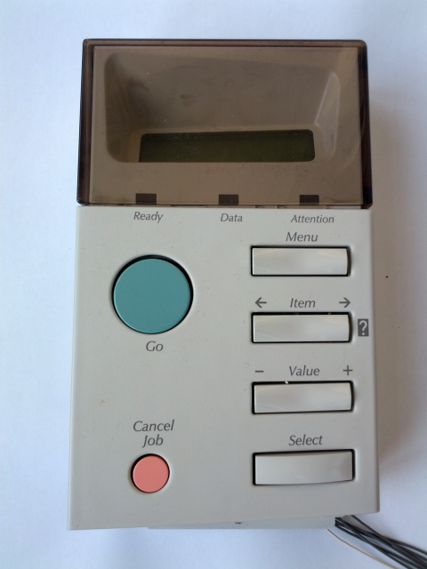
Here is front panel from HP LaserJet 4500 printer. It has 2×16 LCD (probably with Hitachi HD66710 controller, but I am not sure because there are no markings on the board) , 3 LED indicators and 9 push buttons.
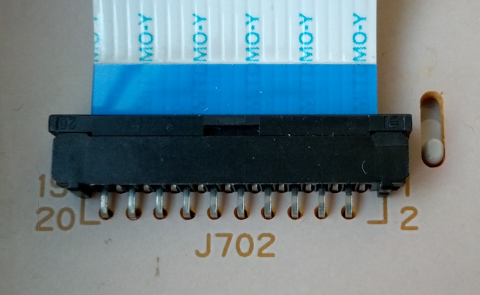
On the back PCB there are 20 pin LCD connector (J702) and 7 pin connector (J701). LCD module also has 20 pin connector (CN1).

CN1 , J702 and J701 pinout:


| Description | 7 pin connector (J701) | 20 pin connector (CN1 and J702) |
|---|---|---|
| GND | 7 | 19 |
| 3.3V | 1 | 18 |
| 5V (backlight) | 2 | 20 |
| SEL | 5 | 14 |
| CLK (SCLK) | 6 | 15 |
| DIN (MOSI) | 4 | 17 |
| DOUT (MISO) | 3 | 16 |
http://playground.arduino.cc/Code/HpLaserJetLcd.
Here you find all information about connecting this panel to Arduino. ( Uses software SPI bit banging ).
I used source code from above site and ported it to STM32F103RBT6 microcontroller development board with hardware full duplex 16bit SPI.
Some notes about LCD :
- No lowercase letters.
- No blinking cursor.
Here is initialization of SPI ( CPU runs 72Mhz, SPI speed is 562.5kHz ):
GPIO_InitTypeDef GPIO_InitStructure;
SPI_InitTypeDef SPI_InitStructure;
NVIC_InitTypeDef NVIC_InitStructure;

_selectPin = GPIO_Pin_4;
_selectPin_gpio = GPIOA;
_clockPin = GPIO_Pin_5;
_clockPin_gpio = GPIOA;
_dataWritePin = GPIO_Pin_7;
_dataWritePin_gpio = GPIOA;
_dataReadPin = GPIO_Pin_6;
_dataReadPin_gpio = GPIOA;

RCC_APB2PeriphClockCmd(RCC_APB2Periph_GPIOA | RCC_APB2Periph_SPI1, ENABLE);

GPIO_StructInit(&GPIO_InitStructure);
GPIO_InitStructure.GPIO_Mode = GPIO_Mode_AF_PP;
GPIO_InitStructure.GPIO_Speed = GPIO_Speed_50MHz;
GPIO_InitStructure.GPIO_Pin = _clockPin | _dataWritePin;
GPIO_Init(GPIOA, &GPIO_InitStructure);

GPIO_StructInit(&GPIO_InitStructure);
GPIO_InitStructure.GPIO_Mode = GPIO_Mode_Out_PP;
GPIO_InitStructure.GPIO_Speed = GPIO_Speed_50MHz;
GPIO_InitStructure.GPIO_Pin = _selectPin;
GPIO_Init(GPIOA, &GPIO_InitStructure);

GPIO_ResetBits(_selectPin_gpio,_selectPin);
GPIO_ResetBits(_clockPin_gpio,_clockPin);
GPIO_ResetBits(_dataWritePin_gpio,_dataWritePin);

GPIO_InitStructure.GPIO_Mode = GPIO_Mode_IN_FLOATING;
GPIO_InitStructure.GPIO_Pin = _dataReadPin;
GPIO_Init(GPIOA, &GPIO_InitStructure);

NVIC_InitStructure.NVIC_IRQChannel = SPI1_IRQn;
NVIC_InitStructure.NVIC_IRQChannelPreemptionPriority = 4;
NVIC_InitStructure.NVIC_IRQChannelSubPriority = 0;
NVIC_InitStructure.NVIC_IRQChannelCmd = ENABLE;
NVIC_Init(&NVIC_InitStructure);

SPI_InitStructure.SPI_Direction = SPI_Direction_2Lines_FullDuplex;
SPI_InitStructure.SPI_Mode = SPI_Mode_Master;
SPI_InitStructure.SPI_DataSize = SPI_DataSize_16b;
SPI_InitStructure.SPI_CPOL = SPI_CPOL_High;
SPI_InitStructure.SPI_CPHA = SPI_CPHA_2Edge;
SPI_InitStructure.SPI_NSS = SPI_NSS_Soft;
SPI_InitStructure.SPI_BaudRatePrescaler = SPI_BaudRatePrescaler_128;
SPI_InitStructure.SPI_FirstBit = SPI_FirstBit_MSB;
SPI_InitStructure.SPI_CRCPolynomial = 7;
SPI_Init(SPI1, &SPI_InitStructure);

SPI_Cmd(SPI1, ENABLE);
SPI_I2S_ITConfig(SPI1, SPI_I2S_IT_RXNE, ENABLE);
Sending data to panel:
void sendLcdByte(uint8_t value, uint8_t mode)
{
  uint16_t wordValue = (mode) ? 0 : 0x80; // State of the RS (0 - Data, 1 - Instructions)
  wordValue |= (uint16_t)_digitalSwitchMask;
  wordValue |= ((uint16_t)(~value)<<8);
  while (SPI_I2S_GetFlagStatus(SPI1, SPI_I2S_FLAG_TXE) == RESET);
  SPI_I2S_SendData(SPI1,wordValue);
  GPIO_SetBits(_selectPin_gpio,_selectPin);
  GPIO_ResetBits(_selectPin_gpio,_selectPin);
  delay_us(50); // commands need > 37us to settle
}
Reading state of the 9 buttons from panel ( 9 bits represent state of 9 buttons ):
extern uint16_t inputValues;

void SPI1_IRQHandler(void) {

  if(SPI_I2S_GetITStatus(SPI1,SPI_I2S_IT_RXNE)==SET)
  {
     inputValues = SPI_I2S_ReceiveData(SPI1) >> 5;
  }
}
The source code for the project is available at my github:HP_4000_4500. The source code is the same for HP 4000 and HP 4500 panels. The only difference is the initialization of the SPI.
Here is video showing demo :
Left button press toggles led. Right button press turns led on and turns led off when released. Select button toggles all three leds. Small red button turns off backlight, and big green button turns the backlight on. On the screen there is a counter that is incremented every millisecond and a “heart” that flashes every second.

Stupid not work example…
There is no magic involved, everything works, you just have to try harder…
Give all the code please.
And read example for right use spi:
// send data
void SPI2_SendByte(uint8_t sendData)
{
while (SPI_I2S_GetFlagStatus(SPI2, SPI_I2S_FLAG_TXE) == RESET);
SPI_I2S_SendData(SPI2, sendData);
}
void ili9341c_SetWindow(uint16_t ystart, uint16_t xstart, uint16_t yend, uint16_t xend)
{
. . .
GPIO_ResetBits(GPIOB, GPIO_Pin_12); // DC=0;
SPI2_SendByte(LCD_PAGE_ADDR);
while (SPI_I2S_GetFlagStatus(SPI2,SPI_FLAG_BSY)!=RESET); //wait send to display
GPIO_SetBits(GPIOB, GPIO_Pin_12); // DC=1;
SPI2_SendByte(xstart>>8);
SPI2_SendByte(xstart&0xFF);
SPI2_SendByte(xend>>8);
SPI2_SendByte(xend&0xFF);
while (SPI_I2S_GetFlagStatus(SPI2,SPI_FLAG_BSY)!=RESET); // wait send
. . .
}
Delay not use!!!!!!!!!!!!!!!!!!!!
& Max speed.
Added link to the full source code.
I do not understand. I send the data, and does not come …. confirmation from the LCD. But the lights turn on.
Hmmm.
What is it needed for connector Sel ? 0 and 1 or 1 and 0
Or 1 sending commands, 0 sending data?
SPI_InitStructure.SPI_DataSize = SPI_DataSize_16b;
&
wordValue |= ((uint16_t)(~value)<<8);
What for???????
GPIO_ResetBits(_selectPin_gpio,_selectPin); This sets the 1?
Thank you for the future response.
>>I do not understand. I send the data, and does not come …. confirmation from the LCD. >>But the lights turn on.
Because SPI is set to full duplex operating mode, confirmation (16 bit data) from the panel ALWAYS comes.
>>What is it needed for connector Sel ? 0 and 1 or 1 and 0
>>Or 1 sending commands, 0 sending data?
To read the digital inputs, SEL must be brought from HIGH to LOW
>>SPI_InitStructure.SPI_DataSize = SPI_DataSize_16b;
>>&
>>wordValue |= ((uint16_t)(~value)<>What for???????
The protocol is described at http://playground.arduino.cc/Code/HpLaserJetLcd
>>GPIO_ResetBits(_selectPin_gpio,_selectPin); This sets the 1?
This brings SEL pin to 0
The link above contains very detail explanation of the communication protocol. What I did is that I took the Arduino library from above link, and ported it to STM32. The original library doesn’t use SPI, it uses pin toggling. At first I also used pin toggling on the STM32, and when everything worked I converted it to SPI mode. One thing I noticed is that I must select right SPI speed and other SPI parameters. It took a lot of time trying and experimenting, but finally all worked.
Thanks you for answers! 😉
I am will try uses pin toggling too. I am use stm32f103c8t6.
In your example you check TXE buffer and wait some ms.
This oddly. TXE – flag empty buffer, but not check transport. Transport is check flag BSY. You send data in buffer and wait, but no check delivering data.